Dieser Leitfaden zu Spritzguss-Schweißnähten erläutert praktische Überlegungen zur Materialauswahl, zur Konstruktionsprüfung, zur Fertigung und zu Beschaffungsentscheidungen.
Was sind Schweißnähte?
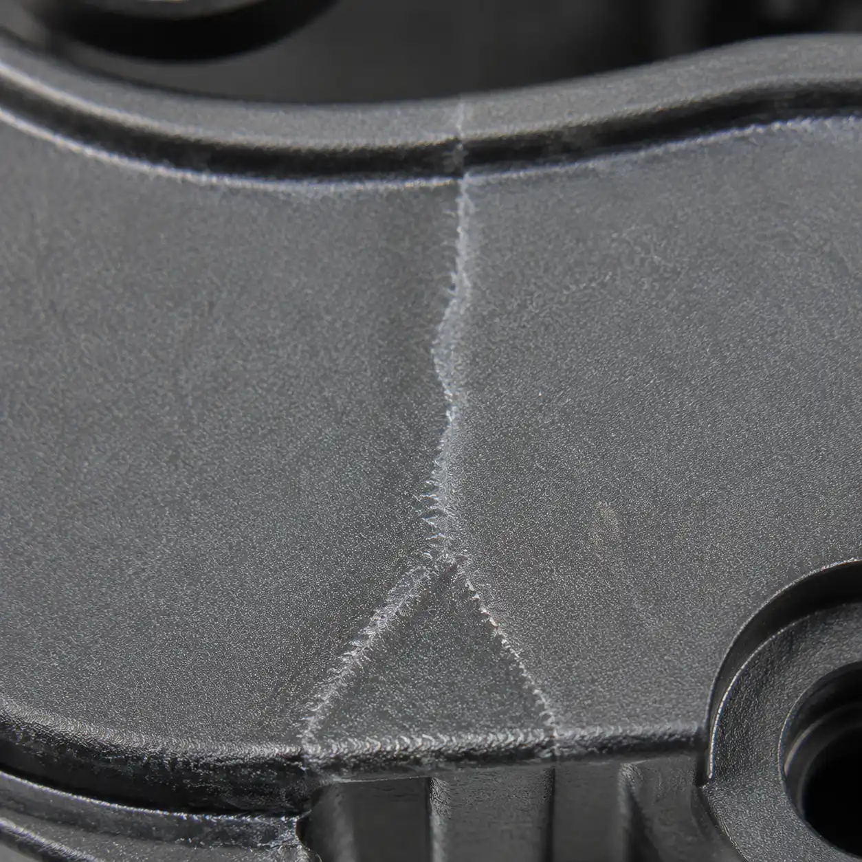
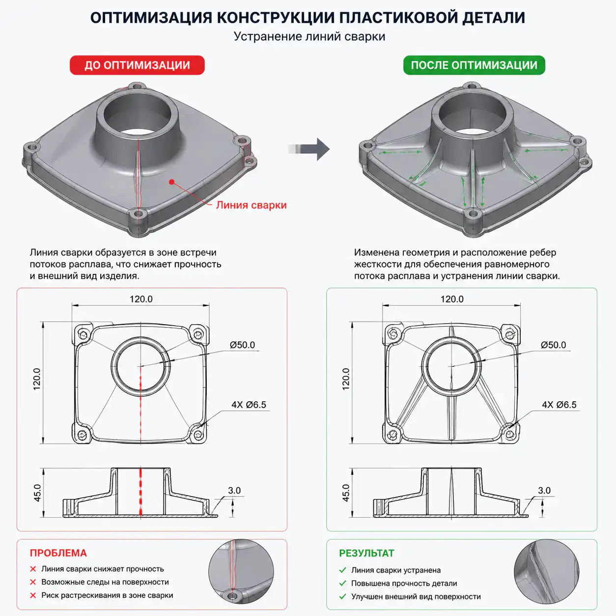
Eine Schweißnaht (auch als Verbindungsnaht bezeichnet) ist ein linearer Defekt, der entsteht, wenn zwei oder mehr Fließfronten aus geschmolzenem Polymer während des Spritzgussprozesses aufeinandertreffen und sich auf molekularer Ebene nicht vollständig vermischen. Das Ergebnis ist eine sichtbare Linie oder eine mechanisch schwächere Zone auf der Oberfläche des Bauteils – und, was noch entscheidender ist, quer durch die Wandstärke.
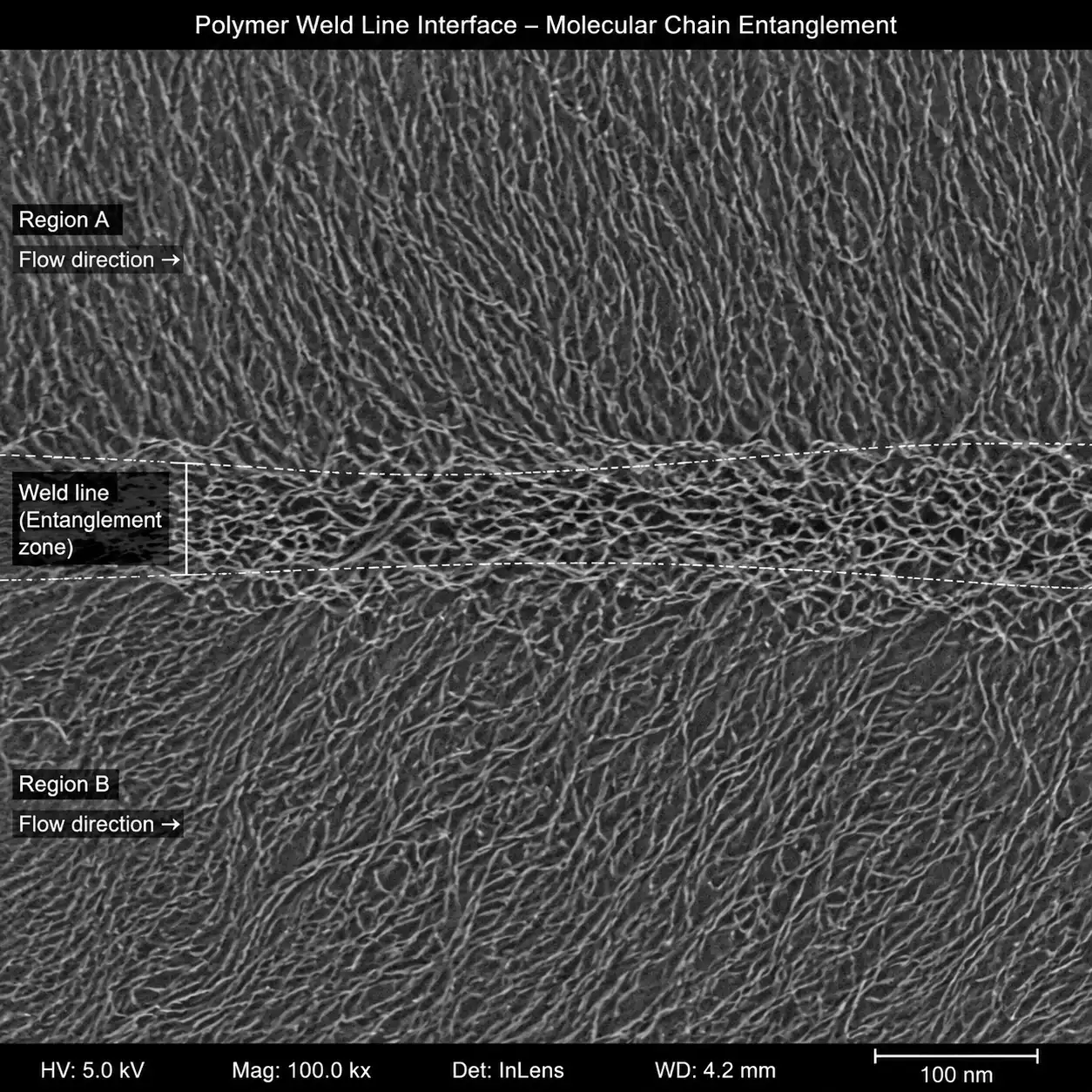
Schweißnähte werden mechanisch definiert als Bereiche mit unvollständiger Verflechtung der Polymerketten. Wenn Strömungsfronten aufeinandertreffen, haben die Polymermoleküle an der vorrückenden Front bereits begonnen, sich abzukühlen und sich parallel zur Strömungsrichtung auszurichten. An der Berührungsfläche stoßen die Ketten von den gegenüberliegenden Seiten lediglich aneinander, anstatt sich gegenseitig zu durchdringen, wodurch eine Grenze entsteht, die sich unter Zug- oder Stoßbelastung wie ein Mikroriss verhält.
Unter den Fehlern beim Spritzgießen stellen Schweißnähte eine besondere Gefahr dar, da sie bei der Sichtprüfung an der Oberfläche oft unbemerkt bleiben, während sie gleichzeitig zu einer Verringerung der lokalen mechanischen Festigkeit um 20-70% führen – was sie zu den #1 – versteckter struktureller Defekt in Formteilen.
Was sind die Ursachen für Schweißnähte?
Schweißnähte entstehen nicht zufällig. Sie bilden sich überall dort, wo sich der Materialfluss während der Formfüllung aufteilt und wieder zusammenfließt. Drei Hauptszenarien sind für über 90% der auftretenden Schweißnähte verantwortlich:
1. Zusammenfluss von Strömungsfronten nach einer Hindernisstruktur (Loch oder Einsatz)
Wenn geschmolzenes Polymer auf einen Kernstift, einen Einsatz oder ein anderes Hindernis im Formhohlraum trifft, teilt sich der Schmelzstrom in zwei Ströme, die das Hindernis umfließen und sich auf der gegenüberliegenden Seite wieder vereinen. Dies ist das häufigste Szenario für Schweißnähte – es tritt bei praktisch jedem Bauteil mit Löchern, Schlitzen oder Metalleinsätzen auf.
2. Multi-Gate-Konvergenz
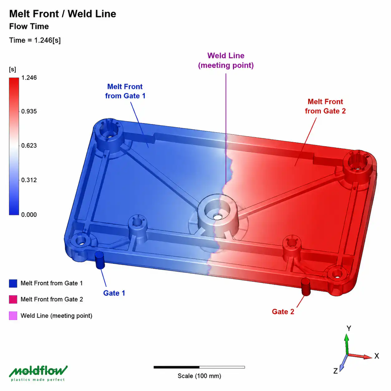
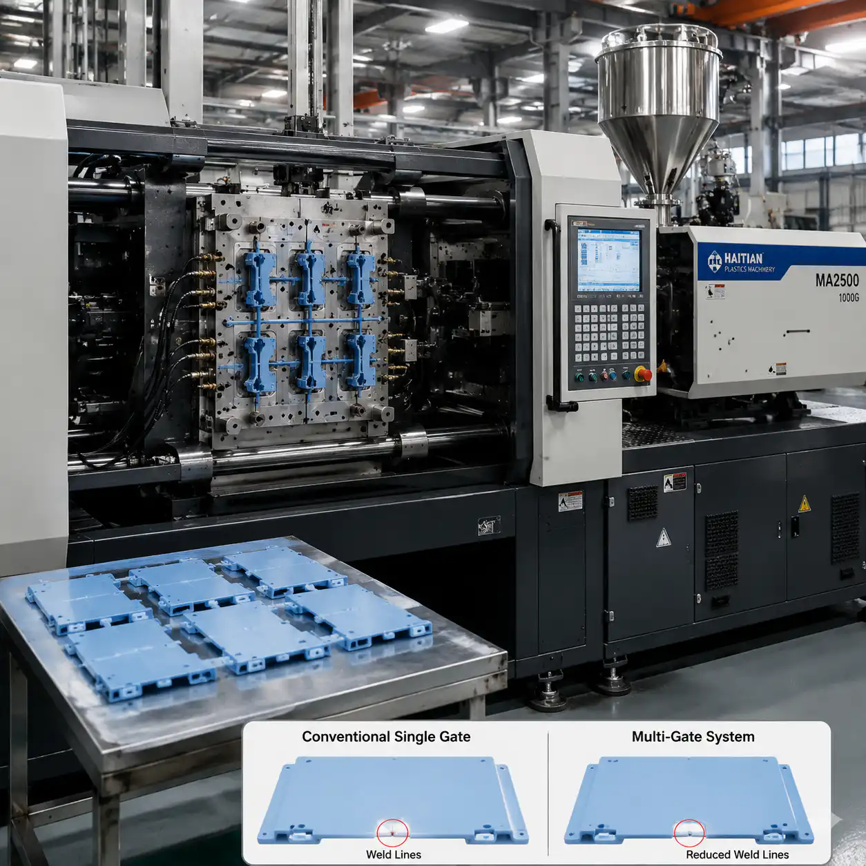
Wird ein Hohlraum gleichzeitig über zwei oder mehr Angussstellen befüllt, treffen die Fließfronten der einzelnen Angussstellen schließlich aufeinander. Die Position und der Winkel dieses Zusammentreffens bestimmen die Schweißnaht. Eine hohe Anzahl von Angussstellen beim Befüllen großer Teile führt fast zwangsläufig zu Schweißnähten, was Optimierung des Gate-Layouts eine entscheidende Designentscheidung.
3. Schwankungen der Wandstärke
Plötzliche Änderungen der Wandstärke führen zu unterschiedlichen Fließgeschwindigkeiten. Das Polymer im dickeren Abschnitt fließt schneller (geringerer Widerstand), überholt den Fluss im dünneren Abschnitt und bildet eine Schweißnaht an der Stelle, an der sich die beiden Fronten wieder vereinen. Dieser Mechanismus ist besonders heimtückisch, da er bei der Konstruktion von Bauteilen oft übersehen wird.
Arten von Schweißnähten: Kalt-, Heiß- und Verbindungsnähte
Nicht alle Schweißnähte sind gleich. Das Verständnis dieses Unterschieds ist für eine ordnungsgemäße Risikobewertung und die Entwicklung von Strategien zur Risikominderung von entscheidender Bedeutung:
| Typ | Formierungstemperatur | Aussehen | Kraftbeibehaltung |
|---|---|---|---|
| Kaltverschweißungsnaht | Unterhalb der Schmelztemperatur | Scharfe, V-förmige Kerbe auf der Oberfläche | 50-70%-Verlust (Worst-Case-Szenario) |
| Heißschweißlinie | Über der Schmelztemperatur | Eine kaum wahrnehmbare Linie, die möglicherweise unsichtbar ist | 10-30%-Verlust |
| Zeile zusammenführen | Nahe der Schmelztemperatur, >135 Grad Treffwinkel | Oft unsichtbar | 5-15%-Verlust (Best-Case-Szenario) |
Kaltverschweißungsnähte entsteht, wenn sich die Strömungsfronten vor ihrem Zusammentreffen erheblich abgekühlt haben – was häufig am Ende des Füllvorgangs, in dünnwandigen Abschnitten oder bei langen Fließwegen der Fall ist. Die Polymerhaut ist bereits erstarrt, sodass nur noch ein dünner geschmolzener Kern zur Verbindung übrig bleibt. Die Folge sind eine scharfe Oberflächenkerbe und eine erhebliche Festigkeitsminderung.
Heiße Schweißnähte entsteht, wenn sich Fronten treffen, während das Material noch vollständig geschmolzen ist, was typischerweise zu einem früheren Zeitpunkt im Füllvorgang geschieht. Die molekulare Diffusion und die Kettenverflechtung sind hier zwar besser, liegen aber immer noch deutlich unter dem Niveau des Volumengutmaterials, da die Ketten an der vorrückenden Front ausgerichtet sind und senkrecht zur Fließrichtung nur eine begrenzte Beweglichkeit aufweisen.
Zeilen zusammenführen stellen eine besondere Unterklasse dar, bei der sich die Fronten in einem spitzen Winkel (über etwa 135 Grad) und bei Temperaturen nahe oder oberhalb des Schmelzpunkts treffen. Der spitze Treffwinkel begünstigt eine bessere Vermischung und eine höhere Verflechtungsdichte, was zu deutlich besseren mechanischen Eigenschaften führt als bei typischen Schweißnähten.
Materialempfindlichkeit: Wie verschiedene Kunststoffe auf Schweißnähte reagieren
Die Festigkeit der Schweißnaht hängt stark vom Grundpolymer ab. Amorphe, teilkristalline und gefüllte Werkstoffe verhalten sich an der Schweißebene völlig unterschiedlich:
| Material | Typ | Erhalt der Festigkeit an der Schweißnaht (%) | Schlüsselverhalten |
|---|---|---|---|
| PA66 (ungefüllt) | teilkristallin | 75-85% | Gute Schweißnahtfestigkeit; Wasserstoffbrückenbindungen unterstützen die Rückstellung |
| PA66 GF30 | Teilkristallin + GF | 50-60% | Die Fasern verlaufen parallel zur Schweißnaht – keine Brückenbildung |
| PA6 | teilkristallin | 70-80% | Ähnlich wie bei PA66 trägt eine etwas niedrigere Tg dazu bei, |
| PP (ungefüllt) | teilkristallin | 80-95% | Excellent weldability; slow crystallization aids healing |
| PP GF30 | Teilkristallin + GF | 45-55% | Glass fibers severely degrade weld strength |
| PC (unbesetzt) | Amorph | 85-95% | Best unfilled weld retention; high melt strength |
| POM | teilkristallin | 60-75% | Fast crystallization hurts; high mold temp helps |
| ABS | Amorph | 80-90% | Good weld retention; rubber phase helps toughness |
| PPS GF40 | Teilkristallin + GF | 35-50% | Worst-case weld strength; avoid structural welds |
The critical takeaway: glass fiber reinforcement amplifies weld line weakness. Fibers at the weld plane align parallel to the interface rather than bridging across it, so the weld region behaves essentially like the unfilled matrix — minus the fiber reinforcement the part was designed to rely on. A PA66 GF30 part may drop from 180 MPa tensile strength to 90-110 MPa at the weld line.
Weld Line Prediction Using Moldflow Simulation
Modern DFM (Design for Manufacturability) workflows make weld lines predictable before steel is cut. Autodesk Moldflow and similar simulation packages can identify all weld line locations during the filling analysis phase. If you want to see how those reports are interpreted, our mold flow analysis and DFM guide breaks down the most useful outputs.
Key Moldflow outputs to examine in your DFM report:
- Weld line result plot: Displays all weld line locations as colored lines. Pay attention to lines in high-stress regions identified by your FEA.
- Temperature at flow front result: The single most important predictor of weld line quality. If the temperature at flow front at the meeting point is above the material’s no-flow temperature, you are in hot weld line territory. Below it, expect a cold weld line.
- Meeting angle: Angles below 90 degrees produce poor entanglement. Angles above 135 degrees are merge-line territory. Most Moldflow packages display this as a numerical overlay.
- Fill time contour: Check whether both flow fronts arrive simultaneously. A time differential means one front is stagnant while the other advances, worsening the weld.
- Air trap result: Weld lines and air traps often coincide. A trapped air pocket at the weld location can create additional voids and burn marks.
A thorough DFM report should flag every weld line location, classify it by predicted severity (temperature + angle + stress location), and recommend specific mitigation for lines in structurally critical zones.
Prevention Strategies: Design-Level Solutions
Preventing weld lines at the design stage is always cheaper than compensating through processing. Here are the primary design-level strategies, ranked by effectiveness:
1. Gate Relocation
The single most powerful lever. Moving the gate changes the entire flow pattern. Relocate gates so that weld lines shift to low-stress, non-cosmetic regions of the part — or, ideally, to the very end of fill where they exit into an overflow well. Even a 5 mm gate position shift can dramatically alter weld line location and severity.
2. Wall Thickness Optimization
Eliminate abrupt thickness transitions that cause differential flow rates. Gradual transitions (3:1 ramp rule) allow flow fronts to stay better synchronized. In multi-thickness parts, consider localized thinning or thickening to steer the weld line position.
3. Flow Leaders and Deflectors
Flow leaders are local wall thickness increases that create preferential flow paths, steering the melt to arrive at the meeting point simultaneously and at higher temperature. This is a targeted, low-cost mold modification compared to gate relocation.
4. Overflow Wells
Position overflow tabs or wells at the weld line location. The weld line forms inside the overflow, which is then trimmed off post-molding. This is the nuclear option — it eliminates the weld line from the functional part entirely — but adds material waste and a secondary trimming operation.
5. Sequential Valve Gating
For multi-gate molds, sequential valve gating opens gates in a programmed sequence rather than simultaneously. This creates a single continuous flow front that sweeps across the cavity, eliminating multi-gate weld lines. The cost is higher tooling complexity and controller hardware, but for large structural parts (automotive bumper beams, instrument panel carriers), it is the standard approach.
Processing Fixes: Optimizing Weld Line Strength Through Parameters
When mold modifications are not feasible (existing tooling, budget constraints, or tight timelines), processing adjustments can improve weld line strength by 10-30%:
| Parameter | Direction | Effect on Weld Line | Beschränkungen |
|---|---|---|---|
| Schmelztemperatur | Increase 10-20 degrees C | Higher temp = better molecular diffusion at meeting plane. Strongest single processing lever. | Material degradation risk, longer cycle time, flash |
| Temperatur der Form | Increase 10-30 degrees C | Slows skin freezing; more time for chain entanglement before solidification | Longer cycle time, dimensional stability concerns |
| Einspritzgeschwindigkeit | Increase (faster fill) | Reduces cooling during filling; fronts meet hotter. Also increases shear heating. | Jetting, burn marks, gas traps, flash |
| Haltedruck | Increase + extend time | Compresses the weld zone; reduces voids and improves density | Flash, overpacking, molded-in stress |
| Gegendruck | Moderate increase | Better melt homogeneity; consistent viscosity aids predictable flow front behavior | Excessive shear heating, fiber breakage in GF materials |
Practical processing sequence for weld line optimization: Start by raising melt and mold temperature to the upper end of the material supplier’s recommended range. Then increase injection speed incrementally while watching for flash and burn marks. Finally, dial in holding pressure and time using short-shot studies to confirm the weld line zone is fully packed. This sequence typically recovers 15-25% of the lost weld strength — not a replacement for good design, but often the difference between passing and failing a structural test.
Testing Weld Line Strength
Verifying weld line performance requires targeted testing. Standard material datasheet values assume no weld lines, so they are dangerously misleading for parts with significant weld zones:
Tensile Testing (ISO 527 / ASTM D638)
Mold tensile bars with the weld line at the gauge center (use a film gate at both ends). Compare weld-line specimen strength to unwelded control specimens from the same mold. The ratio gives you actual weld line strength retention for your material, mold, and process combination. This should be standard procedure for any structural part with weld lines.
Impact Testing (ISO 179 / ASTM D256)
Weld lines are especially damaging to impact strength — often showing 70-90% reduction even in materials with good tensile weld retention. Charpy or Izod specimens notched at the weld line location provide critical safety validation for parts subject to shock loading.
Visual Inspection Standards
For cosmetic surfaces, establish clear accept/reject criteria. Dimensional standards like DIN 16742 provide classification systems for weld line visibility. Generally: Class A surfaces (visible in use) should show no visible weld line groove under specified lighting; Class B surfaces (visible but non-cosmetic) allow a faint line; Class C surfaces (hidden) have no cosmetic restriction but still require mechanical validation. Surface texture and gloss targets also matter here, which we cover in the Leitfaden zur Oberflächenbearbeitung.
For detailed PA66 GF30 properties and grade selection, see our glass-filled nylon grade comparison guide covering GF15, GF30, and GF60 stiffness, heat, warpage, and molding data.
Häufig gestellte Fragen
Sind Schweißnähte immer schlecht, oder sind sie manchmal akzeptabel?
Weld lines are not universally catastrophic. In non-structural, non-cosmetic regions of a part they are often acceptable without modification. The key question is: Is the stress at the weld line location below the reduced strength of the weld zone? In a PC enclosure with a hole for a cable pass-through in a low-stress area, a weld line is likely fine. In a PA66 GF30 engine mount bracket with the weld line at the bolt hole — where vibration and tensile loads concentrate — it is almost certainly a failure risk. Always apply the location-based risk assessment: stress level at weld line multiplied by weld strength retention equals actual safety factor. If that safety factor is below your design requirement, the weld line is unacceptable.
Wie stark nimmt die Festigkeit einer Schweißnaht bei PA66 GF30 ab?
In PA66 with 30% glass fiber, tensile strength at the weld line typically drops to 50-60% of the unwelded material strength. For a typical PA66 GF30 with 170-190 MPa tensile strength, the weld line zone strength is approximately 85-115 MPa. Impact strength reduction is even more severe — often down to 20-30% of the unwelded value — because glass fibers at the weld plane provide essentially zero bridging across the interface. The polymer matrix alone must carry the load. This is why GF materials demand the most aggressive weld line mitigation strategy, and why weld line location must be a primary consideration during gate placement design for any glass-filled material.
Können Schweißnähte vollständig beseitigt werden?
In parts with holes, inserts, or multiple gates, weld lines cannot be completely eliminated in a physical sense — you are always splitting and recombining flow. However, you can effectively eliminate their mechanical impact through: (1) Overflow wells that shunt the weld line into a disposable tab, physically removing it from the functional part. (2) Sequential valve gating that creates a single uninterrupted flow front for multi-gate parts. (3) Design changes that shift the weld line to a non-structural zone where strength reduction is irrelevant. The phrase “weld-line-free part” in DFM reports usually means “no weld line in any functionally critical location,” not literal absence.
Wie genau ist Moldflow bei der Vorhersage der Lage von Schweißnähten?
Moldflow weld line location prediction is highly reliable — typically within 1-3 mm of the actual position on the molded part when the mesh is properly refined and process settings match production. The location accuracy comes from the solver’s ability to track flow front advancement, which is fundamentally correct physics. Strength prediction is less reliable and should be treated as a comparative ranking tool, not an absolute predictor. Moldflow’s weld line strength outputs are based on empirical correlations with meeting angle and temperature at the flow front and should be validated with physical tensile bar testing for safety-critical applications. For DFM purposes: trust the location, verify the strength prediction with real molded specimens.