Insert molding versus overmolding is a process-selection decision based on the substrate, interface, load, material compatibility, tooling, automation and test requirement. Insert molding encapsulates a preformed component such as metal, wire, mesh or another rigid part. Overmolding adds a second polymer layer to a substrate, often to provide grip, sealing, protection, insulation or a soft-touch surface. Both can be single-shot or multi-stage processes, and both need retention and interface evidence.
Use insert molding when a preformed component must be positioned and surrounded by plastic. Use overmolding when a second polymer layer must cover or join a substrate. Chemical adhesion may help, but it is not the only design route: mechanical interlocks, holes, undercuts, ribs and controlled compression can provide retention when the materials do not chemically bond.
The decision should be made before tooling because the substrate handling, interface shutoff and inspection route can change the mold architecture. A two-shot tool may reduce handling but increase investment and service complexity. A separate insert-transfer route may be easier to change, but it adds a handling step and a second opportunity for position error. Compare the total delivered cost, not only the first tool quotation.
For the dedicated two-shot process, see the two-shot molding guide; this page remains the comparison point for selecting between the major interface strategies.
Direct process-selection answer
| Frage | Insert molding is favored when | Overmolding is favored when |
|---|---|---|
| What is the substrate? | Metal, wire, mesh, threaded insert or rigid preformed component | Rigid plastic, elastomer, cable, grip substrate or molded polymer base |
| What is the function? | Thread, conductivity, structural retention, wear or electrical connection | Grip, seal, insulation, cushioning, protection or tactile surface |
| What holds the interface? | Encapsulation, holes, knurl, undercut or mechanical lock | Chemical bond, interlock, compression, wrap-around or combination |
| What drives tooling? | Insert loading, location, clamping, shielding and removal | Substrate transfer, interface shutoff, two-shot rotation or second shot |
| What must be tested? | Insert position, pullout, torque, insulation and dimensions | Peel, pull, shear, compression, environmental aging and appearance |
Read the insert molding guide for metal-insert details and the overmolding guide for bonding and tool design. This comparison page keeps both services separate and focuses on choosing the correct process before the RFQ and tool concept are approved.
Process and tooling comparison
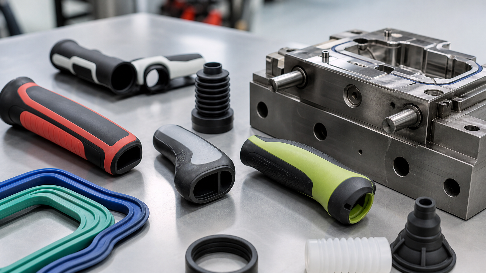
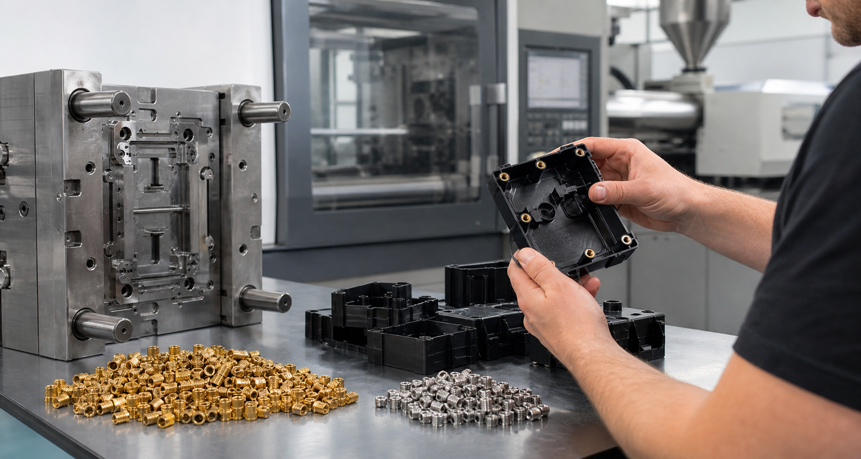
In insert molding, the preformed component must be loaded, located and held during injection. The mold must prevent movement, protect functional surfaces and avoid damaging wires, terminals or threads. Insert temperature, orientation, clearance, venting, encapsulation thickness and removal method affect the result. Manual loading may be suitable for low volume, while automation or poka-yoke location becomes important as volume increases.
In overmolding, the substrate must be clean, dimensionally stable and presented in a repeatable position. The tool must control the interface, gate, vent, shutoff, flash and the route by which the second material reaches the substrate. Two-shot molding can transfer a molded substrate within the same machine and tool, while insert-transfer or separate-shot processes may use a robot or operator. The choice affects cycle, alignment, handling and cost.
Material and insert compatibility
Material compatibility should be tested at the actual grade and condition. A material family name is not enough because additives, plasticizer, filler, colorant, moisture, surface finish and processing temperature can change the interface. Rigid substrates may be PC, ABS, PA, PBT, PP, metal or a finished component. Overmolds may be TPE, TPU, silicone or another rigid polymer.
| Compatibility factor | Why it matters | Evidence to request |
|---|---|---|
| Polymer chemistry | Controls potential chemical adhesion and interface stability | Grade pair, supplier compatibility data and molded-coupon test |
| Surface preparation | Oil, oxide, release agent, moisture and texture alter adhesion | Cleaning, plasma/primer if used, roughness and storage condition |
| Thermal window | Second-shot heat may distort or degrade the substrate | Substrate heat history, mold temperature and dimensional change |
| Mechanical retention | Provides load transfer when chemical bond is limited | Interlock geometry, embedment, pullout and peel evidence |
| Environmental exposure | Heat, fluids, humidity and cycling can weaken the interface | Exposure conditions, aging duration and post-test strength |
Bonding, retention and interface design
A bonded interface should specify whether the requirement is peel, pull, shear, torsion, compression, sealing or a combination. Design the interface with enough area and a controlled transition. Avoid a sharp bond edge that concentrates peel stress. Mechanical locks can use holes, grooves, ribs, undercuts or wrap-around features, but they need draft, fill access, venting and ejection review.
For metal inserts, knurl, hole, flange, head shape and encapsulation length can control pullout and rotation. The plastic around the insert must cool without voids or sink that reduce the load path. For soft overmolds, the substrate may need a positive stop, texture, channel or undercut so the layer cannot peel during use. Flash at the interface can affect sealing and appearance even when the bond strength is acceptable.
Cost, cycle, automation and volume
| Faktor | Insert molding | Overmolding | Decision question |
|---|---|---|---|
| Werkzeugbau | Insert nests, location, shielding and encapsulation | Interface shutoffs, transfer, gates, vents and second material path | Which system controls alignment and flash at production volume? |
| Cycle | Insert load and removal can dominate cycle | Second shot, transfer or substrate cooling can dominate cycle | What is the real cycle including handling? |
| Automation | Insert feeding, orientation and presence detection | Substrate transfer, robot handling and part orientation | Can the interface be loaded repeatably without damage? |
| Scrap risk | Lost insert plus molded plastic may increase cost | Bond/flash failure can scrap the completed assembly | Which failure mode is easier to detect before value is added? |
| Umfang | Manual loading may suit low volume; automation suits scale | Two-shot or transfer tooling may justify higher investment | Does lifetime volume support the selected tooling route? |
Tolerance and failure risks
Insert position is affected by insert tolerance, nest clearance, injection pressure, thermal expansion, shrinkage and handling. Define true position, rotation, exposed length, encapsulation thickness and any electrical or sealing datum. Overmold dimensions depend on substrate size, overmold shrinkage, interface cooling, tool temperature and the restraint created by the substrate. Inspect the finished assembly at the defined conditioning state.
Common failures include insert shift, cracked plastic around a metal feature, voids, flash, delamination, peel, short fill, trapped gas, substrate distortion and color/texture mismatch. A process change may reduce one symptom but create another. Use cross-sections, pull/peel/torque tests, environmental aging and cavity/lot traceability to confirm the actual mechanism.
Application decision tree
- Define the substrate: metal or preformed component suggests insert molding; rigid polymer or grip substrate suggests overmolding.
- Define the interface: state chemical bond, mechanical retention, encapsulation, sealing or insulation requirement.
- Define the load: list pullout, peel, torque, shear, compression, insertion and service cycles.
- Define the environment: state temperature, fluids, humidity, UV, cleaning and aging exposure.
- Compare the tool route: evaluate insert loading, transfer, two-shot, automation, gates, vents and shutoffs.
- Approve the test: set acceptance before tool release and use production-intent grades and substrates.
RFQ checklist
- Provide substrate/insert grade, dimensions, finish, tolerance and storage condition.
- Provide overmold grade, color, texture, shrinkage and processing range.
- Mark interface area, interlocks, bond target, sealing zones and cosmetic requirements.
- State pullout, peel, torque, shear, compression and environmental tests.
- State annual/lifetime volume, cycle, automation, packaging and inspection.
- Request a cross-section, gate/vent/shutoff concept, material evidence and trial plan.
For an RFQ, send both material data sheets, CAD, controlled drawing, interface loads, environmental exposure, volume, color/texture and required tests. We can then compare insert molding, overmolding and two-shot molding against bond risk, retention, cost, cycle and automation before production release.
Häufig gestellte Fragen
Is insert molding the same as overmolding?
No. Insert molding encapsulates a preformed component such as metal or wire. Overmolding adds a second polymer layer to a substrate. The processes can share tooling principles, but interface, loading and validation requirements differ.
Can plastic be overmolded onto metal?
Yes. The metal surface, temperature, geometry, encapsulation, bond/retention strategy and environmental requirement must be validated. Mechanical retention may be required when chemical adhesion is limited.
Which process costs more?
It depends on volume, substrate handling, tool complexity, automation, cycle and scrap value. Insert molding may need precise feeding and nests; overmolding may need transfer, two-shot or interface tooling.
How is adhesion validated?
Use project-specific peel, pull, shear, torque, compression and environmental tests with production-intent materials and defined conditioning. Inspect the interface and failure mode, not only the peak force.
What files are needed for a quote?
Provide CAD, drawing, both material grades, interface geometry, loads, tests, color/texture, annual volume, automation, packaging and environmental conditions.
Insert molding vs overmolding comparison: use the interface load, substrate, material compatibility and validation requirement to select the process before tooling.