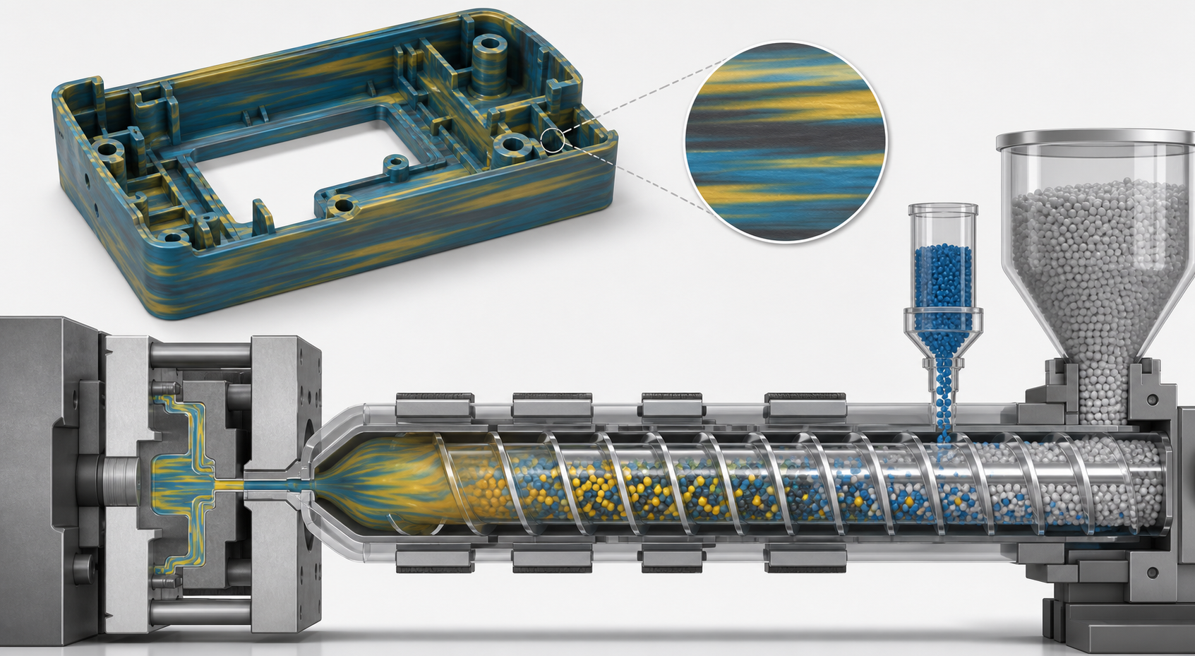
Color streaks in injection molding are visible bands, swirls, cloudy zones or uneven color caused by incomplete dispersion, unstable dosing, degraded material, contamination, poor purge practice or a flow path that exposes color differences. The same symptom can also be mistaken for splay, burn marks or weld-line shading. Changing the melt temperature without identifying the mechanism can make the color defect worse.
For a buyer, color quality should be defined as a material and process requirement, not only as a visual preference. Specify the resin grade, color standard, masterbatch or pre-colored compound, approved Delta E range when applicable, lighting condition, viewing distance, cosmetic zones and lot traceability. A supplier can then distinguish a true mixing problem from a deliberate fiber pattern, texture effect or variation between approved samples.
What color streaks look like and why they matter
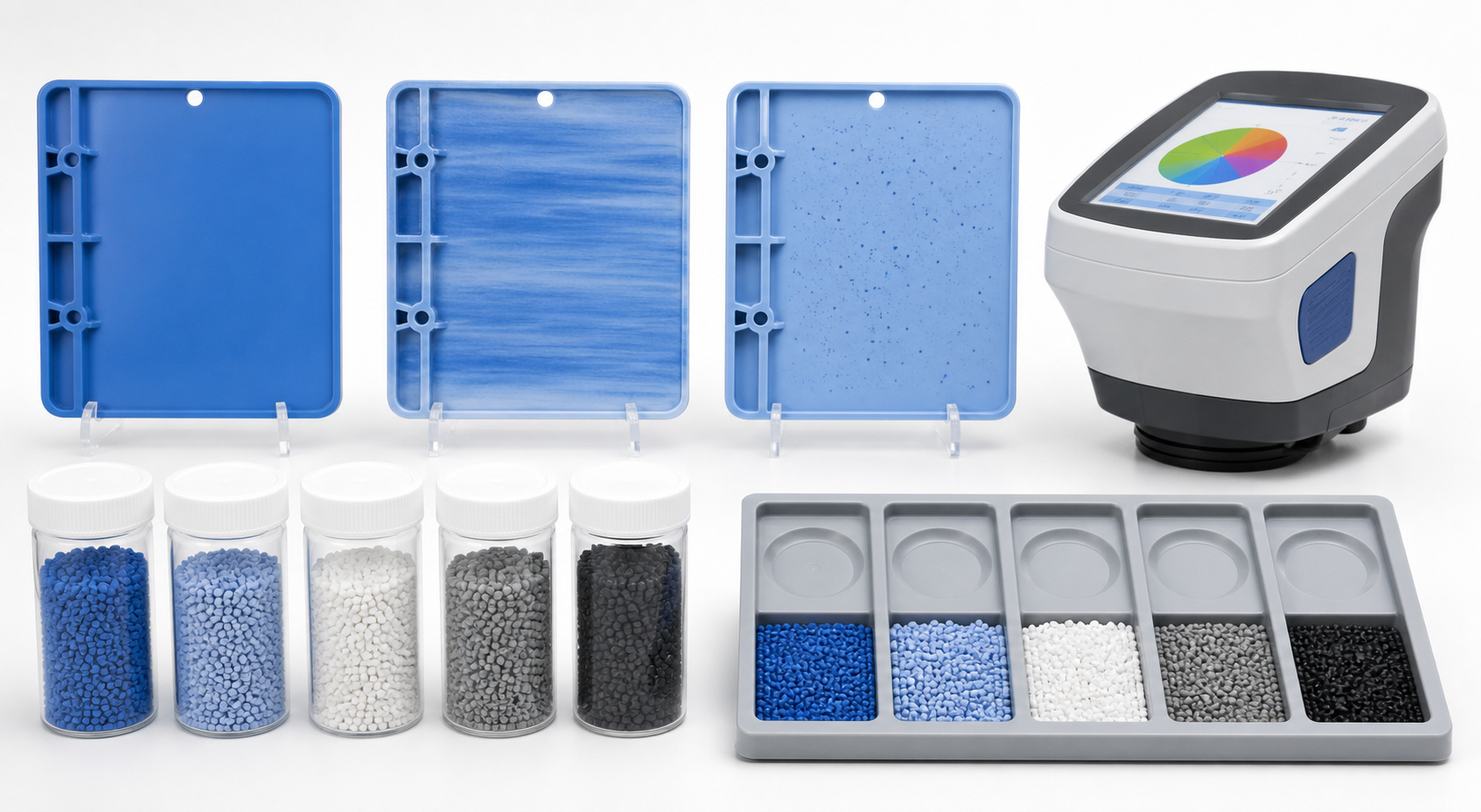
Streaks may run in the flow direction, appear as cloudy bands, show a dark tail behind a rib, or form a marbled transition after a color change. They can be uniform across all cavities or appear in only one cavity. Longitudinal streaks often point toward mixing, dosing or flow shear. Random specks suggest contamination or degraded residue. A color difference near a weld line may be caused by orientation, cooling, surface texture or two flow fronts meeting rather than poor pigment dispersion.
Color defects are not always cosmetic only. In a transparent or translucent part, uneven pigment can change light transmission. In a product with a controlled color code, the defect can indicate wrong material or dosing. In a filled compound, a streak may show poor distribution of a conductive, flame-retardant or reinforcing package. Traceability and functional testing should therefore be part of the investigation when the color also signals material identity.
Separate color streaks from similar surface defects
| Observed feature | Likely direction | Confirmation method |
|---|---|---|
| Long bands in flow direction | Dispersion, dosing or shear-related mixing | Review screw recovery, back pressure and masterbatch ratio |
| Silver or cloudy streaks | Moisture or gas splay | Check drying, moisture level and a controlled dry-material trial |
| Dark spots or black specks | Contamination or degraded residue | Inspect hopper, barrel, purge, regrind and material transfer path |
| Color change near weld line | Flow-front joining, orientation or cooling | Compare gate layout, short shots and weld-line location |
| Patch after color change | Dead spot, poor purge or incompatible carryover | Retain purge samples and inspect nozzle, screw and hot runner |
| Only one cavity affected | Cavity runner, gate or hot-runner imbalance | Compare cavity samples and cavity-specific flow paths |
Use the color customization service page for color development and approval requirements, the common injection molding defects guide for the broader defect map, and the injection molding service page for the production route. This page owns the diagnosis of streaking, dispersion and contamination in molded parts.
Color-streak cause, evidence and corrective action
| Cause group | Evidence to collect | Correction direction |
|---|---|---|
| Material and masterbatch | Resin grade, pigment carrier, lot, moisture, dosage and compatibility | Confirm material identity, dosing ratio, drying and approved color system |
| Maschine | Screw speed, back pressure, recovery time, melt temperature and residence time | Improve mixing without excessive shear or degradation and stabilize recovery |
| Material handling | Hopper cleanliness, regrind, conveying line, feeder calibration and color-change record | Clean the path, control regrind and calibrate dosing equipment |
| Mold and hot runner | Dead spots, runner balance, gate shear, hot-runner zones and cavity pattern | Remove stagnation, balance flow or repair a hot-runner location that retains residue |
| Teilegeometrie | Wall transitions, ribs, weld lines, texture and flow direction | Review gate, flow path and cosmetic-zone design before changing pigment |
Do not assume that more back pressure always improves color. It may improve dispersion in one material system but increase residence time, shear heat or degradation in another. Likewise, a higher screw speed can reduce recovery time yet raise shear. Each trial should record actual recovery time, melt temperature, shot weight, color measurement and visual comparison.
Diagnostic sequence for a color complaint
- Define the reference. Identify the approved master sample, color standard, lighting, viewing distance and cosmetic zone.
- Map the defect. Photograph each cavity and mark whether streaks follow flow, a weld line, a rib, a gate or a random location.
- Check material identity. Verify resin, colorant, masterbatch, lot, drying and any regrind or mixed material.
- Review dosing. Confirm feeder calibration, gravimetric or volumetric setting, hopper bridging and actual ratio.
- Run a purge audit. Retain purge samples before, during and after cleaning; note black specks, old color and unmelted pellets.
- Review screw recovery. Compare back pressure, screw speed, recovery time, cushion and residence time against the stable process.
- Compare cavities. A single-cavity pattern points toward runner, gate, vent or hot-runner differences.
A controlled color trial should change one variable group at a time. First confirm material and dosing. Then test purge and residence-time controls. Only after those checks should the team evaluate back pressure, screw speed, melt temperature or gate shear. A colorimeter or spectrophotometer can quantify change, but measurement geometry and sample surface must remain consistent.
Process corrections for dispersion and contamination
For dispersion problems, the goal is enough mixing to distribute the colorant without overheating the polymer. Adjust back pressure and screw speed within the grade’s processing range, then verify that the melt temperature remains stable. For contamination, cleaning and material segregation are more important than adding heat. A dirty hopper, conveying line, nozzle or hot-runner branch can reintroduce residue after a clean purge.
- Calibrate the masterbatch feeder and confirm the actual dosing ratio.
- Use a controlled purge sequence when changing colors or polymers.
- Reduce dead time in the barrel, hot runner and transfer path.
- Check screw, non-return valve, nozzle and hot-runner surfaces for retained material.
- Control regrind identity, percentage and color segregation.
- Record color data at first-off, steady-state and restart conditions.
Mold and DFM factors
Flow geometry can make a properly mixed melt look streaked. A thin gate or abrupt thickness transition may create local shear and a visible color band. A long runner or hot-runner branch can retain previous material. A weld line can show different gloss or orientation even when the color is chemically uniform. For cosmetic parts, gate location, runner balance, wall thickness and texture should be reviewed before the tool is released.
If a conductive, flame-retardant or fiber-filled color compound is used, confirm that the correction does not change the functional additive distribution. A visually uniform surface can still fail resistance, flame, mechanical or dielectric testing if the formulation or dosing is wrong. Material certificates and lot traceability are as important as the color sample.
Validation and acceptance plan
Define the acceptance method before a supplier starts the trial. Record color standard, instrument or visual method, light source, angle, sample preparation and allowed color difference. Inspect the first-off sample, steady-state samples, restart samples and every cavity. Keep an approved boundary sample when the product uses visual acceptance rather than a single numeric limit.
For repeat production, connect color approval to material lot, masterbatch lot, dosing setting, purge record and process window. A supplier should identify when a color change is complete, how many shots are discarded, and which sample is used for release. When color indicates a technical compound, add the relevant resistance, flame or mechanical test rather than approving appearance alone.
Color-streak prevention and RFQ checklist
- Provide the color standard, approved sample, cosmetic zones and lighting condition.
- State resin grade, colorant system, masterbatch ratio and approved substitutes.
- Identify whether regrind is allowed and how it must be segregated.
- Send CAD with gate, flow direction, texture and transparent areas marked.
- Ask for feeder calibration, purge method and color-change control.
- Define cavity-specific color inspection and lot traceability.
- State Delta E or visual limits and any functional property linked to color.
- Request first-off, steady-state, restart and boundary samples for approval.
For an RFQ or corrective-action request, provide photos, color standard, resin and grade, cavity number, process sheet, drawing, annual volume, prior approved sample and the production event that preceded the streaking. This lets the supplier separate a dosing issue from a mold flow or contamination issue.
Häufig gestellte Fragen
What is the fastest way to confirm color streaks and poor mixing?
Compare the streak direction with material flow, verify dosing and material identity, retain purge samples, and inspect screw recovery and cavity patterns. A controlled color trial should use the same resin and reference standard.
Can color streaks and poor mixing be fixed by process settings alone?
Sometimes. Stable dosing, controlled back pressure, screw speed and residence time can improve dispersion. Contamination, dead spots, incompatible material or a flow-path problem requires cleaning, material control or mold review.
When does color streaking require a mold modification?
Consider mold work when the pattern follows a gate, runner, hot-runner branch, weld line or cavity-specific flow path and remains after material, purge and process controls are stable.
How should color streaks be measured or accepted?
Use an approved color standard with a defined visual condition or colorimeter method. Record instrument geometry, sample surface, lighting, allowed color difference, cavity and material lot.
What files should a supplier receive before troubleshooting?
Provide photos, CAD, drawing, color standard, resin and grade, masterbatch information, cavity and shot data, process history, material records, annual volume and the affected cosmetic or functional requirement.