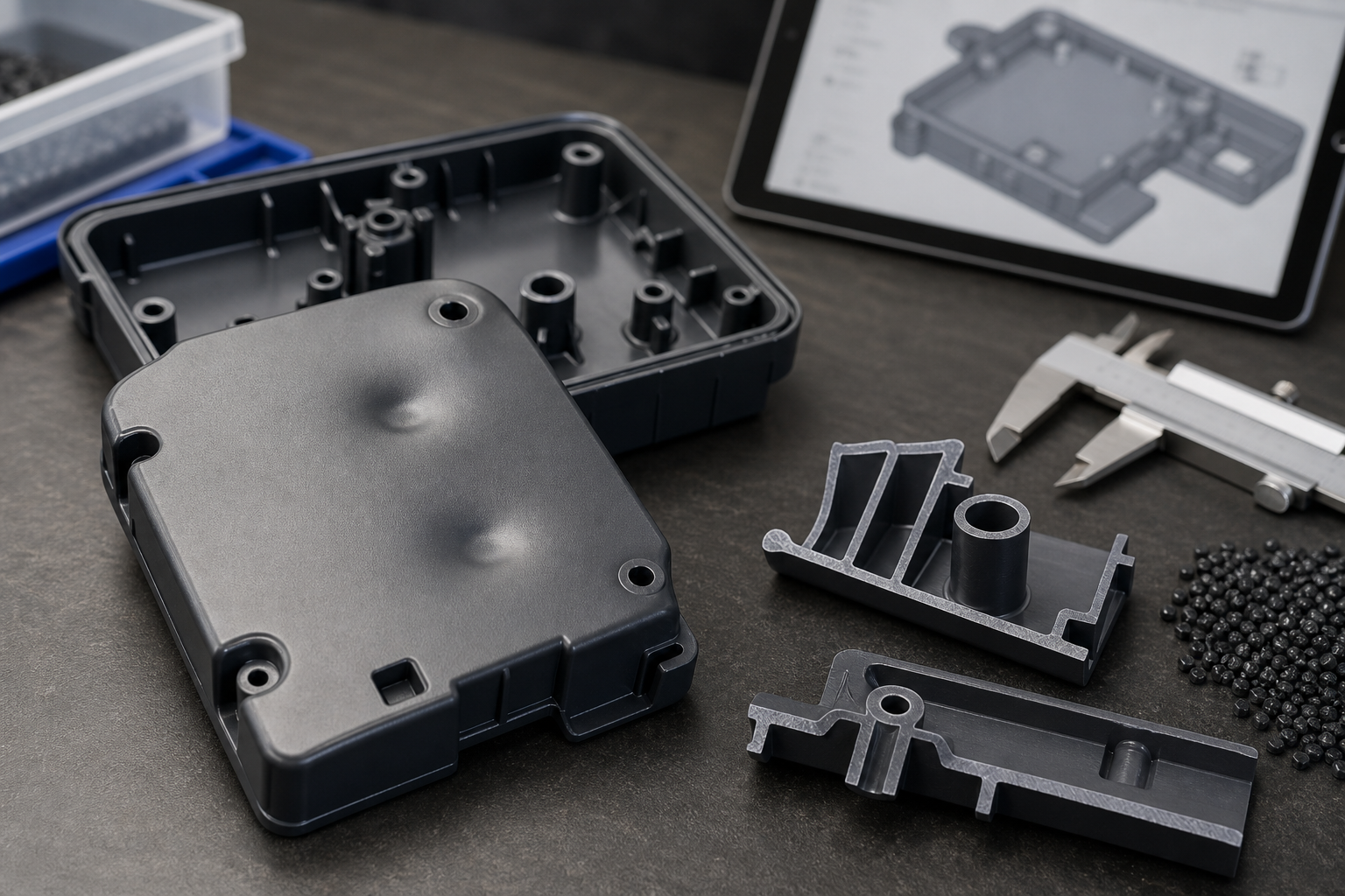
Ribs and bosses for injection molding should carry load with controlled thickness, draft, radii, spacing and support without creating sink marks, voids, warpage, cracking or ejection damage. A rib increases stiffness and controls the load path. A boss provides a location for a screw, insert, pin, standoff or alignment feature. Both can become local thick sections that cool and shrink differently from the surrounding wall.
For a buyer, the useful DFM review connects the feature to the nominal wall, resin shrinkage, fastener or load requirement, cosmetic surface and mold direction. A supplier should explain whether the feature needs coring, a gusset, a metal insert, a different fastener, a local wall change or post-machining. The goal is a part that is strong and dimensionally stable, not simply a thicker feature that hides a short-term assembly problem.
The engineering function of ribs and bosses
| Funktion | Engineering purpose | Evidence to review | Risk when oversized or unsupported |
|---|---|---|---|
| Rib | Stiffens a wall and carries bending or shear load | Load path, wall thickness, rib height, radius, draft and flow direction | Sink, void, warpage, weld line or ejection stress |
| Boss | Supports screw, insert, pin, standoff or alignment | Fastener, torque/pullout, core, wall connection and datum | Sink, cracking, stripped thread, distortion or poor insert fit |
| Gusset | Supports a rib/boss and spreads load into the wall | Base thickness, spacing, draft and cosmetic-side effect | Local thick mass, sink, stress concentration or tool access issue |
| Cored feature | Removes material from a thick region and shortens cooling path | Core strength, venting, ejection, hole size and tool motion | Breakage, void, flash, weak wall or difficult machining |
| Metal insert | Provides threads, wear, conductivity or high load capability | Insert geometry, placement, retention, heating and molding process | Distortion, insert shift, stress, corrosion or added cycle |
Use the sink-mark guide when a rib or boss is already producing a cosmetic depression. The warpage guide helps when the feature pulls a panel out of plane. The draft angle guide covers release and ejection around deep ribs, bosses and cores.
Inputs that control the design
Start with the load path and the nominal wall. A rib should connect to the wall where stiffness is needed, but its mass should remain controlled relative to that wall. A boss should connect to a structural region or be supported with ribs/gussets when torque or pullout is high. If the fastener load is significant, confirm whether molded plastic threads, thread-forming screws, heat-set inserts or molded-in metal inserts are appropriate.
Resin shrinkage, stiffness, creep, moisture response and reinforcement change the design decision. Glass-filled grades may provide stiffness and reduce some shrinkage, but they can increase anisotropy, tool wear and stress sensitivity. Unfilled materials may need a larger load-bearing section but can be more forgiving in ejection. Nylon can change dimensions with moisture, so boss position, hole size and torque acceptance should state the conditioning state.
- Nominal wall, load path, rib/boss height, base radius and draft.
- Resin grade, filler, shrinkage, creep, moisture and operating temperature.
- Fastener type, torque, pullout, strip resistance, insert method and service cycles.
- Cosmetic face opposite the feature, sink limit and acceptable surface variation.
- Gate, flow direction, weld-line location, cooling and packing requirements.
- Tool opening direction, core access, ejection, automation and annual volume.
Geometry rules for ribs and bosses
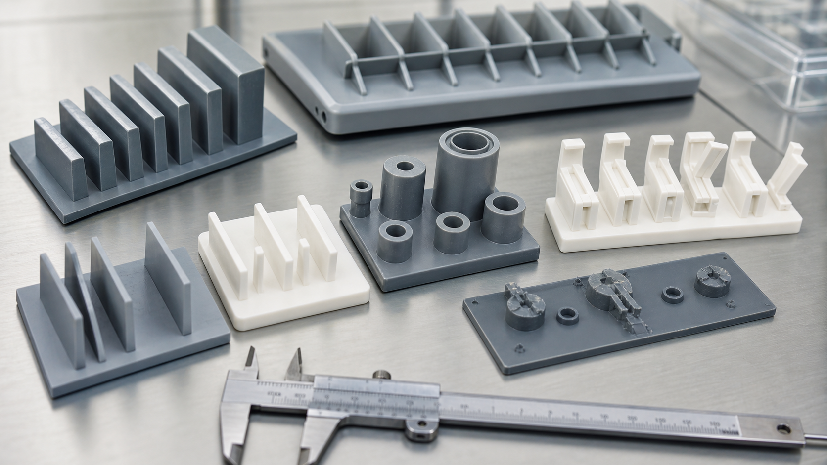
Keep ribs thinner than the wall when the cosmetic surface is important, and use a generous base radius that avoids a sharp stress concentration. The exact ratio depends on resin, texture, load, wall, cooling and appearance requirements; do not approve a universal ratio without a drawing-specific review. A rib that is too thin may not fill or may be weak. A rib that is too thick may create a sink mark on the opposite face.
Bosses should normally be cored so the wall around the hole does not become a heavy mass. Review the outside diameter, core diameter, height, base radius, draft and connection to the wall. If the boss must carry torque, use ribs or gussets strategically rather than increasing the entire boss wall. Spacing between bosses and adjacent walls matters because nearby features can merge their thermal and stress effects.
Gussets should be placed where they carry load without creating a large local thickness. Their base should transition smoothly into the wall and have enough draft for release. Avoid four-way thick intersections where a rib, boss, wall and gusset meet at one point. Add core relief, separate the load paths or use an insert if the function requires more material than injection molding can cool uniformly.
Material and production-volume effects
| Material or condition | Rib/boss concern | Design response | Validation focus |
|---|---|---|---|
| Glass-filled resin | Directional shrinkage, stiffness, fiber orientation and tool wear | Review flow, gate, support, radius, steel and torque direction | Flow/transverse dimensions, warpage, cracking and tool wear |
| Unfilled resin | Higher shrinkage or creep may reduce boss and thread stability | Review load, fastener, wall support and service temperature | Torque, pullout, creep and conditioned dimensions |
| Nylon or moisture-sensitive resin | Hole, boss position and torque can change with moisture | Define drying, conditioning and inspection state | Mass, humidity, dimensions and functional test |
| High-temperature resin | Thermal shrinkage, tool temperature and insert compatibility | Use resin-specific processing and validate insert/cycle design | Heat-aged dimensions, strength and release |
| High-volume production | Repeated torque, ejection, tool wear and cycle consistency | Define inserts, wear surfaces, maintenance and process window | Long-run samples, torque trend, cavity balance and defect rate |
Tooling options and cost trade-offs
A cored boss is usually less risky than a solid boss because it reduces mass and cooling demand, but the core must be strong, aligned, vented and supported. A gusset can improve load transfer at lower mass than a thicker wall. A metal insert can provide durable threads or wear resistance, but it adds purchasing, placement, preheating or post-molding operations and may create a thermal sink or flow obstruction.
| Option | Nutzen Sie | Trade-off | Suitable when |
|---|---|---|---|
| Controlled rib | Adds stiffness with limited material | Needs draft, radius, cooling and cosmetic review | Wall needs bending or panel stiffness |
| Cored boss | Supports a fastener with lower mass | Core strength, draft and insert/ejection access | Plastic boss can meet torque and pullout |
| Gusset support | Spreads load from boss or rib into the wall | Can create sink or a complex local tool area | Load path needs support without thickening the boss |
| Molded metal insert | Provides durable thread, wear or conductivity | Added cost, placement, thermal and tolerance controls | Plastic threads cannot meet service requirements |
| Post-machined feature | Improves hole or thread precision after molding | Secondary operation, datum and cost control | Critical accuracy exceeds molded capability |
Failure modes and corrective actions
Sink marks appear when a heavy rib or boss continues to shrink after the surface has frozen. Voids can form inside a thick feature when the outside skin seals before the core material is fed. Warpage can occur when the feature pulls one side of a panel or changes the local cooling pattern. Cracking may come from sharp radii, excessive ejection, insert stress, a brittle grade or an over-tightened fastener. Stripped threads or boss fracture indicate that the fastener and material system need review, not only a larger boss.
Corrective action may include coring, reducing feature thickness, adding a radius, moving a rib, changing gate or packing, improving cooling, changing the fastener or using an insert. Increasing hold pressure can reduce a sink mark in some cases, but it may create flash, stress or warpage and cannot correct a fundamentally heavy geometry. Validate the part against appearance, dimensions and the actual torque/pullout requirement.
Validation at DFM, mold trial and approval
- DFM thickness map: compare nominal wall, rib/boss sections, opposite cosmetic face and cooling access.
- Load review: state fastener, torque, pullout, shear, service temperature and cycle requirement.
- Trial sections: inspect sink, voids, weld lines and feature geometry; section retained samples when needed.
- Dimensional check: measure boss position, hole, thread, rib profile, flatness and assembly datum after conditioning.
- Functional test: run torque, pullout, insertion, fatigue or mating checks appropriate to the application.
- Production approval: compare cavities, consecutive shots, material lots and the approved process window.
DFM checklist and RFQ data package
- Provide CAD, controlled drawing, resin, grade, texture, annual volume and tool-life target.
- Mark nominal wall, ribs, bosses, load paths, cosmetic faces and sink limits.
- State fastener/insertion method, torque, pullout, load, cycle and service temperature.
- Request thickness map, core/gusset proposal, draft, radius and cooling review.
- Define sectioning, dimensional, cosmetic, torque and pullout acceptance evidence.
- State automation, mold destination, maintenance access and any post-machining operation.
For an RFQ, include the fastener or insert specification and the actual assembly load, not only a boss diameter. We can then choose a rib, gusset, cored boss, metal insert or secondary operation that balances strength, appearance, cooling, tooling and repeatable inspection.
Häufig gestellte Fragen
How do ribs and bosses affect tooling cost?
Simple ribs and cored bosses are usually economical, while deep cores, slides, inserts, special cooling or post-machining add cost. The right choice can reduce sink, ejection damage and assembly failures over the tool life.
Which drawing notes are needed for ribs and bosses?
State nominal wall, feature height and thickness, draft, radius, datums, cosmetic limits, fastener/insert method, torque, pullout, service temperature and conditioning state for inspection.
How do glass-filled resins change ribs and bosses?
They can improve stiffness but add directional shrinkage, fiber orientation and tool wear. Review load direction, gate, cooling, radius, steel and cavity-specific dimensions before approving the feature.
When should the mold concept change instead of adjusting process settings?
Change the concept when a rib or boss remains too thick to cool, sink/voids persist inside the stable process window, the feature cracks under the required load, or a cored boss or insert is needed for function.
How are ribs and bosses validated during mold trials?
Use a thickness map, cosmetic inspection, sectioned samples when necessary, conditioned dimensions, assembly checks, torque/pullout testing and consecutive samples from every cavity.